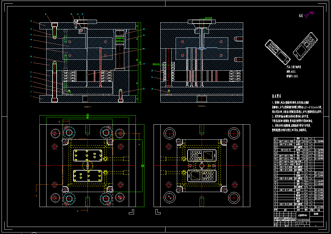
The Importance of Drawing Design for Injection Molds
2025-05-30
The Importance of Drawing Design for Injection Molds

1. The cornerstone of design accuracy and function realization
Geometric accuracy control
Critical tolerance: The tolerance of key matching parts must reach ±0.01mm (such as guide pin holes and cavity parting surfaces) to ensure mold closing accuracy;
Microstructure definition: The drawing marking of the exhaust groove depth of 0.02-0.03mm and width of 0.5-1mm avoids melt trapping;
Thermal deformation compensation: The core size compensation value is reversed through CAE simulation shrinkage rate (0.3%-0.8%) and marked on the drawing.
Functional integrated design
Conformal water channel topology (8-12mm from the cavity surface, temperature difference ≤±1.5℃);
In-mold sensor embedding position (pressure/temperature probe hole position accuracy ±0.05mm).
2. Source optimization of manufacturing efficiency and cost control
Process chain connectivity
Processing path planning: 3D printing priority areas (conformal water channels) and CNC finishing areas (sliding surfaces) are marked on the drawings;
Standardized component call: HASCO/HRS standard part numbers are marked in the detailed list to shorten the procurement cycle by 40%.
Material waste suppression
Mold frame size optimization (reducing steel usage by 15-20% through topological subtractive design);
Insert block strategy (partial replacement instead of overall scrapping, reducing maintenance costs by 60%).
3. Technical archive value for full life cycle management
Maintenance reference benchmark
Wear allowable value marking (such as ejector hole diameter expansion limit +0.03mm);
Surface treatment process requirements (nitriding layer thickness 0.1-0.15mm, HV≥1000).
Iteration upgrade basis
Version control field (such as V2.1-2025 marking the mold modification location and reason);
Mold flow analysis defect record (historical tracing of weld line position correction).
4. New paradigm of digital collaboration in 2025
In-depth application of MBD (model-based definition)
Three-dimensional annotation system replaces two-dimensional drawings (PMI information is directly written in STEP format);
Lightweight model (JT format) realizes real-time collaborative review of the supply chain.
Breakthrough in AI-assisted design
Defect prediction engine (input product STL automatically marks risk areas);
Cost optimization algorithm (recommends economical steel combinations based on historical data).
Key points of injection mold drawing design
Injection mold drawing design is a key link in mold manufacturing, which directly affects product quality and production efficiency. The following are the core points in the design process:
1. Product analysis
Structural review: Check whether the draft angle (usually 1°~3°), wall thickness uniformity (avoid shrinkage marks), ribs and buckles are reasonable.
Material properties: Reserve size compensation according to material shrinkage rate (such as ABS about 0.5%, PP about 1.5%).
Parting line determination: Prioritize the maximum projection edge of the product contour, avoid the appearance surface, and use curved surface parting when necessary.
2. Mold structure design
Parting surface design: Ensure that there is no undercut, usually perpendicular to the mold opening direction of the injection molding machine, and complex parting surfaces require 3D simulation verification.
Cavity layout: Balanced runner design (H-type or radial type), multi-cavity molds need to consider hot runner systems (such as needle valve hot nozzles).
Ejector system: ejector diameter ≥φ2mm, spacing ≤50mm, complex structures need to be equipped with push plates or air tops.
Cooling system: water channel diameter φ6~12mm, 1.5~2 times the diameter from the cavity surface, using series + parallel combination to ensure temperature difference <5℃.
3. Detailed drawing specifications
Dimension marking: key matching parts are marked with tolerances (such as mandrel H7/g6), non-critical dimensions are IT12~14.
Surface treatment: cavity Ra≤0.2μm, etched area needs to be marked with texture number (such as VDI3400 standard).
Steel marking: mold cores are commonly used P20 (pre-hardened) and NAK80 (mirror), and sliders are quenched with S136 HRC52.
4. Manufacturing process considerations
Processing feasibility: electrode splitting needs to consider CNC clearing capabilities (minimum R0.3mm), and deep cavity structures reserve EDM processing allowances.
Standardized components: DME/HASCO standard ejectors and guide pins are preferred (such as φ12mm guide pins with φ16mm guide sleeves).
5. DFM verification
Moldflow analysis: Use Moldflow to verify the filling time (generally <3s) and cavitation position (exhaust grooves are required, 0.02~0.04mm deep).
Interference check: Dynamically simulate the movement of the slider/tilt to ensure no collision.
6. Drawing output requirements
View configuration: Includes exploded view, cross-section view (focus on cooling circuit), and local magnification view (precision structure).
BOM list: Detailed record of heat treatment requirements (such as quenching HRC48-52) and purchased parts brands (such as Parker seals).
Common design traps to avoid:
Avoid sharp corners (minimum R0.5mm) to prevent stress cracking
Tilted top angle ≤12° to prevent jamming
Large molds require hoisting holes (above M16)
Previous:PC lampshade production process

