How to Weld Flanged Pipe Correctly?

Welding Flanged Pipe demands more than a strong arc and a clean bead. It requires controlled fit-up, correct alignment, suitable filler metal, and disciplined inspection. A flange face may look square before welding, then shift after heat enters the joint. That small movement can create leakage, bolt stress, or difficult field assembly.

Industry standards provide the foundation. ASME B31.3 covers process piping requirements, while ASME BPVC Section IX addresses welding procedure and welder qualification. ISO 9606-1 also defines qualification requirements for welders. These standards do not replace judgment. Real pipework includes uneven wall thickness, restricted access, contaminated surfaces, and changing site temperatures.

Workforce data makes this subject more urgent. The American Welding Society and Deloitte projected a potential shortage of approximately 330,000 welding professionals in the United States by 2028. The U.S. Bureau of Labor Statistics also reports continuing demand for welders and related workers. More work does not justify faster shortcuts. It increases the need for repeatable methods and documented competence.

A reliable Welding Flanged Pipe procedure begins with material verification and flange protection. Check the pipe schedule, flange rating, bevel geometry, root opening, and bolt-hole orientation. Use controlled tack welds, balanced welding sequences, and the qualified heat range. Keep weld spatter away from the sealing face. It sounds simple.

It is not always simple.

Even experienced fabricators can overlook distortion after several passes. That is why visual inspection, dimensional checks, and appropriate nondestructive testing should follow the approved procedure. This guide explains the practical decisions behind sound flange welds, while acknowledging an uncomfortable truth: good workmanship still needs verification.
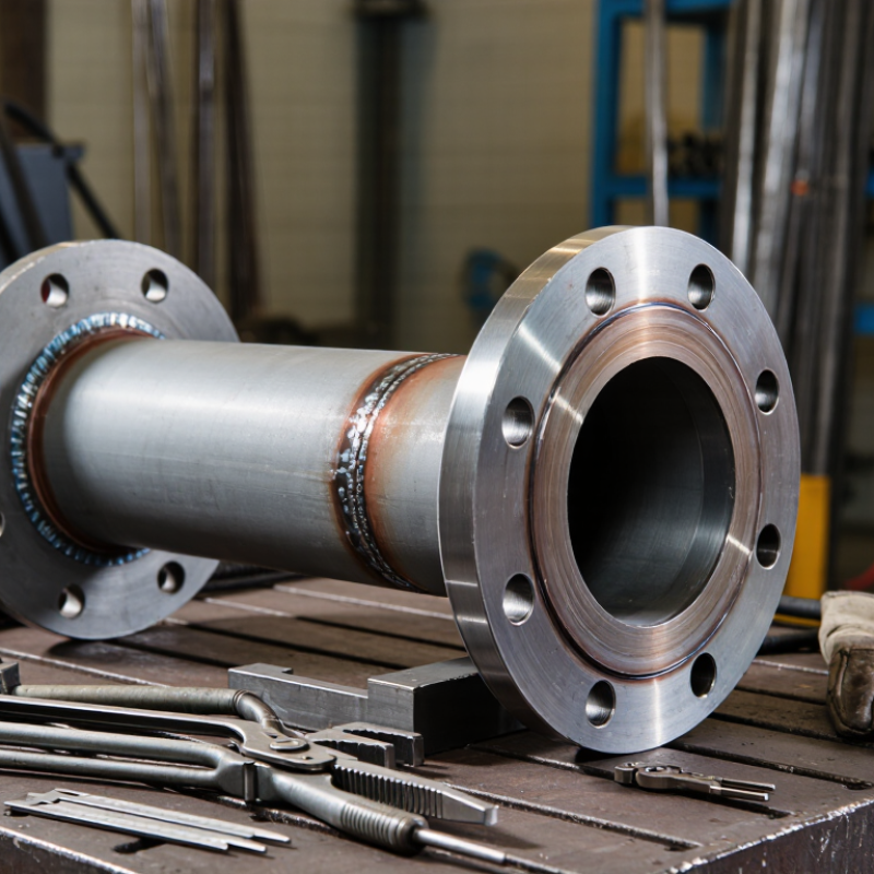
How to Weld Flanged Pipe Correctly?

Verify Pipe, Flange Class, and Weld Materials Against ASME B16.5 and B16.25

Correct flange welding starts with verification, not the arc. Read the pipe marking and record size, schedule, wall thickness, grade, and heat number. Compare those details with the flange marking and purchase documents. ASME B16.5 covers flange dimensions, pressure-temperature ratings, facing, tolerances, and marking requirements. Confirm the flange class matches design conditions, not merely the pipe diameter. Check bore and facing before fit-up. A small mismatch can create poor flow or uneven gasket loading.

ASME B16.25 addresses butt-welding end preparations, including bevel geometry and tolerances. Measure the bevel with a gauge. Do not trust appearance alone. Welding materials require equal attention. Confirm the pipe and flange grades, then select filler metal through the approved WPS. The filler should support strength, corrosion resistance, and service temperature requirements. Review material certificates, consumable classification, storage condition, and heat-treatment requirements. ASME B16.5 and B16.25 do not replace welding procedure qualification. Use the applicable construction code and qualified WPS/PQR. A compatible-looking rod is not enough.

During fit-up, clean the bevels and control root gap, hi-lo, and tack spacing. Keep flange faces protected from spatter. Check bolt-hole orientation before welding. This mistake is surprisingly common. After welding, inspect alignment and surface condition before pressure testing. If records are incomplete, stop and verify them. Rushing here saves minutes, but can create expensive rework.

How to Weld Flanged Pipe Correctly? - Verify Pipe, Flange Class, and Weld Materials Against ASME B16.5 and B16.25
Practical dimensional and material verification table for butt-welded flanged pipe assemblies
Verification Area Applicable Requirement Example Data Acceptance / Welding Check
Pipe size and outside diameter Confirm the nominal pipe size and outside diameter before selecting the flange bore and weld-end preparation. NPS 2 pipe
Outside diameter: 60.3 mm
The flange bore and pipe OD must be compatible. Do not identify the pipe by nominal size alone.
Pipe wall thickness Verify the schedule or specified wall thickness against the approved piping specification and design calculations. NPS 2, Schedule 40
Nominal wall: 3.91 mm
Approximate ID: 52.5 mm
Measure actual wall thickness where required. The weld procedure, heat input, and joint fit-up must suit the actual thickness.
Flange standard and pressure class Use ASME B16.5 for pipe flanges and flanged fittings from NPS 1/2 through NPS 24. Confirm the class and material group. ASME B16.5
NPS 2, Class 150
Welding neck, raised face
“Class 150” is a pressure-temperature designation, not a fixed 150 psi allowable pressure. Check the applicable B16.5 material pressure-temperature table.
Flange dimensions Verify outside diameter, bolt circle, bolt-hole quantity, bolt-hole diameter, thickness, facing, and bore against the applicable ASME B16.5 table. Typical NPS 2 Class 150 reference dimensions:
Outside diameter: 152.4 mm
Bolt circle: 120.7 mm
Bolting: 4 × 15.9 mm nominal bolts
Raised-face height: approximately 1.6 mm
Use the flange manufacturer’s certified dimensional drawing and the current ASME B16.5 edition for final inspection. Bore dimensions may vary with the connected pipe wall and flange series.
Flange material Confirm the material specification, grade, heat number, and pressure-temperature rating. ASME B16.5 provides dimensional and rating requirements; it does not replace the material specification. Carbon-steel example:
Forged flange material: ASTM A105N
Material certificate: required
Match the flange material to the piping design, service temperature, corrosion requirements, and approved material list. Confirm heat treatment and impact-test requirements when applicable.
Pipe material Verify the pipe specification, grade, heat number, wall thickness, and condition before welding. Carbon-steel example:
Pipe material: ASTM A106 Grade B
NPS 2, Schedule 40
Check that the pipe and flange materials are approved as a compatible weld combination by the qualified welding procedure.
Butt-weld end preparation Use ASME B16.25 for butt-welding-end dimensions and tolerances, including bevel configuration and alignment requirements. Common carbon-steel preparation reference:
Included bevel angle: approximately 75°
Bevel angle per side: approximately 37.5°
Root face and root gap: as specified by the qualified WPS
Do not rely on a generic bevel value for every wall thickness. Measure bevel angle, root face, root opening, hi-low, and flange squareness before welding.
Welding process and filler metal Select the process and filler metal using an approved WPS qualified in accordance with the project’s governing welding code, commonly ASME BPVC Section IX. Example process: GTAW root / SMAW fill and cap
Example filler: AWS E7018 for compatible carbon-steel fill and cap passes
Filler selection must be confirmed by the WPS, base-metal group, service conditions, hydrogen-control requirements, preheat, interpass temperature, and post-weld heat-treatment requirements.
Weld consumable control Control consumable identification, storage, drying, exposure time, and batch traceability according to the applicable specification and approved welding procedure. Low-hydrogen electrodes such as E7018 require controlled storage and rebaking or holding conditions when specified by the project procedure. Record electrode classification, lot number, issue time, storage temperature, and welder identification where required.
Flange alignment and orientation The flange face must remain square to the pipe axis and the bolt-hole orientation must match the installation drawing. Inspection points:
Face squareness
Angular rotation
Pipe projection
Internal bore transition
Prevent excessive forced fit-up. Verify bolt-hole orientation before tack welding, and protect the raised face from arc strikes, spatter, and distortion.
Pre-weld and post-weld inspection Inspection scope is governed by the project specification, design code, and approved inspection and test plan. Typical checks:
Visual examination: 100%
Dimensional inspection: before and after welding
NDE: as specified, such as RT, UT, MT, or PT
Confirm weld profile, undercut, surface defects, flange distortion, bore condition, and final dimensional compliance before pressure testing or service.
Important: ASME B16.5 primarily covers flange dimensions, facing, bolting, materials, and pressure-temperature ratings. ASME B16.25 covers butt-welding-end dimensions and preparation. Welding processes, filler metals, preheat, interpass temperature, inspection, and acceptance criteria must be established by the approved project specifications, qualified WPS/PQR, and applicable construction code.

Align Flanges Within ASME B16.5 Tolerances Before Tack Welding

How to Weld Flanged Pipe Correctly?

Align flanges within ASME B16.5 tolerances before tack welding. Clean both flange faces, pipe ends, and bevels before fitting. Remove oil, rust, moisture, and loose scale. Place the flanges on a stable surface, then check their faces with a calibrated straightedge. The faces should remain parallel, and bolt holes should align without forcing the pipe.

Measure the root gap at several points around the joint. Uneven spacing often indicates angular misalignment or poor fit-up. Do not correct it by tightening bolts or using excessive force. Reposition the pipe instead. Check flange rotation with a level or alignment gauge. Then apply evenly spaced tack welds using the approved welding procedure. Recheck alignment after each tack. Heat can move the assembly more than expected. A small shortcut here can create serious stress later.

Tips: Use four balanced tack welds before adding intermediate tacks. Keep the flange protected from weld spatter. Confirm the applicable ASME B16.5 edition and project tolerances before welding. A calibrated gap gauge is better than visual judgment. Also inspect the flange sealing face after fit-up. Even careful work can miss a slight high spot. Pause and measure again.

Set Preheat and Interpass Temperatures per ASME B31.3 and WPS Limits

How to Weld Flanged Pipe Correctly?

Set preheat and interpass temperatures according to ASME B31.3 and the approved WPS. ASME B31.3 establishes process requirements, but it does not provide one universal temperature for every flange. The WPS must reflect material grade, thickness, welding process, hydrogen control, and qualified procedure limits. ASME BPVC Section IX requires these essential variables to remain within qualified ranges.

For example, an illustrative carbon-steel WPS may specify 95°C minimum preheat and 230°C maximum interpass temperature. Confirm the actual values before welding. Measure preheat on the flange body, not only beside the joint. Keep the temperature uniform around the circumference.

Industry guidance from the International Institute of Welding links hydrogen cracking risk with hard microstructures, diffusible hydrogen, and restraint. A thick flange creates considerable restraint. Too little preheat can promote cracking. Excessive heat can reduce strength or distort the flange face.

Tips: Use calibrated temperature crayons or contact thermometers. Record readings before each pass. Remove moisture, oil, and scale from the bevel. Maintain low-hydrogen consumables under controlled storage. Let the joint cool gradually. Do not guess interpass temperature by touch. Review the WPS, material certificate, and welder qualification together. A common field mistake is checking temperature only once. That practice needs reconsideration, especially during long welds and changing weather. Independent inspection reports often identify poor temperature records as a recurring traceability weakness.

Apply Qualified Weld Sequences Using AWS D1.1 or ASME Section IX

How to Weld Flanged Pipe Correctly?

A reliable flange weld begins with a qualified Welding Procedure Specification. AWS D1.1 and ASME Section IX require proven variables, including base metal group, filler metal, preheat, and heat input. A welder should verify the procedure before striking an arc. ASME Section IX qualification records provide traceable evidence, while AWS D1.1 supports structural weld control. Industry failure investigations repeatedly identify distortion and incomplete fusion as major repair drivers. Small errors become expensive quickly.

Clean the pipe bevel and flange face thoroughly. Leave the flange bolting holes protected from spatter. Fit the flange using a calibrated alignment tool, then place balanced tack welds at four opposing points. Use a controlled sequence, such as alternating quadrants, to reduce angular distortion. Keep interpass temperature within the approved range. Excessive heat can pull the flange out of alignment. I have seen a perfect-looking root pass fail after cooling.

Tips: Record preheat readings on the weld map. Measure flange face runout before and after welding. Use low-hydrogen electrodes only when the qualified procedure permits them. Inspect the root visually, then apply the required nondestructive examination. A 2023 U.S. Bureau of Labor Statistics report recorded thousands of occupational injuries involving metalwork and welding-related tasks, reinforcing the need for controlled handling, ventilation, and face protection. Do not rely on habit alone. Recheck the sequence when pipe diameter, wall thickness, or restraint changes.

Inspect Welds with VT, PT, RT, or UT to Applicable Code Acceptance Criteria

How to Weld Flanged Pipe Correctly?

Flange welding starts with alignment, but acceptance depends on disciplined inspection. Confirm the flange face, bore, gap, and bolt-hole orientation before welding. A small angular error can create uneven gasket loading and future leakage. After cleaning, perform visual testing (VT) under suitable lighting. Check the root profile, cap width, undercut, overlap, arc strikes, and crater cracks. ASNT’s 2023 NDT Global Market Outlook valued the global nondestructive testing market above US$20 billion, reflecting how critical inspection has become across pressure-system construction.

VT is only the first filter. Apply penetrant testing (PT) when the applicable code requires surface-breaking crack detection on nonporous weld areas. PT cannot reveal buried defects. Radiographic testing (RT) can identify volumetric discontinuities, while ultrasonic testing (UT) can locate planar flaws and estimate their position.

Select the method according to material, thickness, geometry, and code requirements, not convenience. ASME BPVC Section V defines examination practices, while the construction code establishes acceptance criteria.

Inspectors should record procedure numbers, equipment settings, examiner qualifications, weld identification, and indications found. A clean report matters.

Do not confuse an indication with rejection. The governing code decides that. A weld may look excellent and still contain an unacceptable lack of fusion.

I have seen inspection plans fail because the flange obstructed probe access. Recheck access before welding.

No method sees everything.

We will help turn your vision into reality

Contact Us